Adventures with a Prototype Board
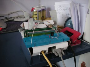
After a fair few days without being able to work on the Weebox, I finally got some spare time last night. Earlier in the week, the nice man from DHL had turned up and delivered my package from RS Electronics containing some resistors, a prototype board and a Vishay infra red detector. Now it was time to get on and build a circuit to plug directly onto my precious TS 7250 board.
I’m not exactly the world’s best electronics expert. Luckily the circuit I needed to get working was simple enough: The detector needed a 5V input, and the output from it needed chopping down from 5V to 3.3V for the weebox. A simple resistive divider on the output was all I needed — that and a way of getting 5V to the chip. The TS7250’s IO ports only supplied 3.3V, so I used a long wire directly over to the input 5V. An old ribbon cable was sacrificed to give me access to the IO input port and ground, and the circuit was built and installed.
Given my initial concerns with my electronics ability, this part went pretty painlessly. Next up though was testing the circuit. I modified some direct IO sample code to print out ‘yay’ on a falling edge and ‘boo’ on a rising edge, then ran it and pointed a remote control at the detector. Hooray! Each keypress gave me a ‘yay’ and a ‘boo’.
As decoding the output from the IR detector requires somewhat finer grained readings than ‘yay’ and ‘boo’, I made some changed to record pulse and space timings. At this point I was still running the demo code, so reading continuously from the IO port to check for changes. I realised that eventually I’d need an interrupt-based system as otherwise I’d miss the data: The pulses and gaps I’m looking at are of the order of 300 microseconds long.
At this point, however, I hit a wall. The pulses and gaps were much longer than I was expecting and there were far fewer than I’d have hoped to have seen. Suspecting my detector circuit I unplugged the wires and started directly holding the IO wire to ground (which should yield a zero). Even that wouldn’t always register, sometimes taking up to a half second to spot I was holding the wires together.
A frustrating few hours of trying everything ensued. I tried different port
settings, assembly code, byte reads, word reads and so on. Nothing made any
difference. I mailed the tech support group but nobody seemed to know what was
going on. Various example programs all exhibited the same problem. I was
stumped. Going back to first principles, I tried to work out what it could be,
assuming it was a software problem. I started to suspect it was a cache problem
as the data seemed to be out of step with what was actually happening. To
confirm my suspicions, I reasoned that if the cache were being put under more
load then there’s more chance that I’d read the actual value rather than the
cached value. I fired up another console and ran ls -lR / | gzip >
/dev/null. Suddenly back in the first console, my program became that
much more responsive. Still not perfect, but my suspicions were confirmed.
At this point I looked around for any cache control instructions for my little program. Sadly none seemed available in user land, and in kernel space I hadn’t seen this problem developing my LCD driver, so I bit the bullet and started on a kernel module. Luckily for me, Andy Gryc from Airchitex had already posted some code for reading interrupts from a GPS device. With very few modifications this was able to read edges from the infra-red device.
With the module loaded, I was able immediately to see that I could count all the pulses and gaps accurately. Hooray! I hastily plugged the infra-red device back in (I was still wire-tapping at this point) and pointed the Xbox remote control at it. Yay! A stream of pulses was recorded!
A bit of tweaking, and some Python post-processing of the data, and I had this:
--____--_-_--_-_----____-____--_-_--____---____-____-____--
Hooray! It was a trace of me pressing ‘1’ on the Xbox keypad, which later (lying in bed) I decoded as 0xace531. Traces of the other keypresses came out as 0 = 0xacf530, 2 = 0xacd532, 3 = 0xacc333 and so on — I’d sussed it! (The ‘1’ seem represented by a short high/low pulse, the zeros with a short high/long low pulse).
My next step is to get this information being decoded in real time — I’m currently looking at getting a LIRC driver written, which looks fairly straightforward from where I am now.