A new screen
It’s been rather a while since I’ve been able to spend any time on the Weebox, what with the Xania.org attack and with work and life intervening (damn them!) However, in the evenings I’ve been researching a new LCD display to replace the frankly quite rubbish 2x24 character display I’m currently using.
Before I go much further I have an admision to make…I’ve actually broken the 2x24 display. It was always a little sensitive to being pushed and pulled about, but after a recent attempt to ‘fix’ it I think I accidentally heat- damaged the underside. Only by bending the whole PCB by about 10 degrees could I get it to work — some solder joint has come undone somewhere. As the screen was never intended to be the final solution this just puhed forwards the point at which I replaced it.
I was looking for a largish screen to display song name, menus, volumes, status messages and the like. I wanted a rectangular screen and ideally a graphical screen instead of a pure character-based screen, so I could do all my favourite games-programmer whizzy effects. Importantly I also wanted something with as few pads to solder as possible (as my soldering skills are limited) and with as few differences from the existing board I had so I could use a lot of the existing LCD support.
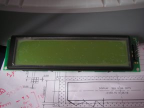
After a lot of looking I found the MGLS-32064. It has an identical pin-out to the HD44780 and has a very similar driver chip, the HD61830. The screen is large and clear, and has a resolution of 320 by 64 pixels. With a decent font that means about 40-50 characters along — ample for my purposes. It also means about 8-10 lines of text; again more than enough. With 8K of character and screen memory it also means I can double-buffer the screen and do flicker- free updates.
I duly ordered the part from RS Electronics, and eagerly awaited its arrival. My original choice of LED backlight was sadly out of stock til November, so I plumped for the non-backlit version. Hopefully I won’t come to regret this decision! I also went to Maplin and bought a new soldering iron — this time temperature-controlled — and some ribbon cable and end-pieces to make my own cables.
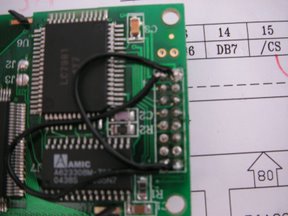
The part arrived and that evening I set about soldering on the pins to the pads. The TS7250 board has an LCD header which provides most of the pins needed, but the chip select and reset pins needed wiring low and high, respectively. After a lot of practice on some stripboard I went on and soldered. Probably the best solderin I’ve ever managed:
All excitedly, and not without some trepidation, I plugged the board in (after first triple-checking the polarity) and turned on the Weebox. A brief flash of the screen (yay), then nothing, as you’d expect. I ran my test program, and I saw something very nearly akin to what I was expecting, some black lines on the screen (sadly I didn’t get a picture). After a bit more investigation and bug fixing in my driver program the screen suddenly went blank. A quick check and two of the wires had come unsoldered — oops.
I reaffixed the wires and double checked the pad connections using my multimeter, resoldering any that appeared a bit dodgy. Back to the board…still nothing.
Many hours of checking and double-checking and comparing with other people’s code and swearing then ensued. But still nothing on the screen. Eventually I wrote a unit test and was able to determine that I could write data to the 8K RAM and then read it back out again absolutely fine, and that I was correctly polling the BUSY flag and that the bit-set and bit-clear operations all worked. Everything on the digital side was working. Only nothing on screen. Tearing my hair out I re-read the less-than-helpful documentation. Oh…pin 3....it’s not really the same as pin 3 on the TS7250. Pin 3 is the VO ‘LCD driver voltage’ on the new display; on the previous screen it was a contrast adjustment. The two amount to the same thing, but whereas the contrast adjustment on the old screen was a 620 Ohm to ground, VO has to be something rather different.
From the spec sheet: ‘VLCD = VDD — VO : range from 14.3V to 15.3V’. Oh dear — a bit of maths indicates that VO has to be minus 9.3V!! A check on google groups confirmed this too, I needed to generate a negative voltage. I’ve mailed RS to tell them their info page is inaccurate — there it specifies the MGLS32064 has an integral DC-DC converter to do such an inversion. I’ve also ordered a 5V -> -12V DC-DC converter, and I hope that wiring that appropriately to pin 3 will bring my display back to life.
As for why I managed limited success at the beginning — I can only suspect that I had original not had pin 3 wired up at all. This in turn might have just fluked it into working, though I’m not sure how. I only hope that I haven’t blown the bloody screen somehow — though the two nearest components to the pad area are the 8K RAM and the controller chip; both of which seem to work fine in my tests.
I’ll be posting once I get any more information, see you next time on Clueless Fool Attempts Electronics! :)